Specifications SailPlan
LOA 7.62 m 25 ft I 9.30 m 30.51 ft
LWL 6.96 m 22.85ft J 2.75 m9.02ft
Beam 2.47 m 8.1ft P 9.50 m 31.16 ft
Draft 1.80 m 5.9ft E 3.72 m 12.2 ft
Displ 930 kg 2050ıb ISP 10.67 m 35.0 ft
Ballast 453 kg 1000ıb SPL 4.20 m 13.78 ft
D/L 77 Crew 5
Up wind sail area 37 m2 400 ft2
Down wind sail area 87.5 m2 940 ft2
Construction Light and simple are the two words used to describe the structure of the Farr 25. All structural elements are stitched/knitted E-glass in an epoxy resin, vacuum-bagged to achieve high fiber contents with low void content. The hull and deck shell is E-glass over a tough foam core, with high-density foam and additional uni-directional and multi-axial reinforcements used in high stress areas. Hull shell support comes from a simple one-piece structural liner, composed of a transverse mast step, transverse keel floor and a single centerline longitudinal spanning from the mast step aft to a composite cockpit support frame. Additional deck support consists of a transverse bowsprit support frame and a shallow foredeck beam. A structural companionway strut supports the deck amidships.
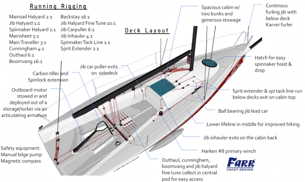
Interior A relatively high freeboard and simplified internal structure provides for a spacious, open interior with sitting headroom on berths port and starboard of the companionway. A low aspect keel trunk is unobtrusively integrated into the centerline longitudinal of the internal structure, allowing for easy movement throughout the cabin. Propulsion is provided by a 6hp outboard, which is conveniently stowed in and deployed through a well in a locker in the cockpit sole.
Keel As seen on most of today’s high tech racing yachts, the keel on the 25 footer is a fixed T-keel configuration with a lead bulb. The builders and designers of the boat considered the various pros and cons of a lifting versus fixed keel configuration, eventually deciding in favor of a fixed keel to keep costs down and have a simple, maintenance free installation. The maximum draft is 1.8m, which does allow the boat to be trailered on its keel throughout Europe and the US. The keel is assembled into a trunk in the hull with a single M20 stainless steel bolt making keel assembly and disassembly extremely easy. The carbon fiber fin is one of the major design features of this yacht. The fin spar is constructed in pre-preg carbon over a foam mandrel, giving incredible stiffness and strength in a very lightweight package. The complete keel fin assembly, including spar, blade and hull attachment fitting weighs a mere 18 kg’s. Such a light fin allows more weight to be packed into the bulb for a lower VCG and turbo’d performance. The fin planform is trapezoidal and utilizes one of FYD’s proprietary custom foil section designs for optimum performance in round the buoys racing. Given the propensity of T-keel configurations to snag kelp and weed, this keel fin also incorporates a kelp cutter installation. The bulb shape takes advantage of the recent CFD research FYD has conducted on bulb shape optimization and features a moderate length to diameter ratio and a high squish ratio for optimum performance in round the buoys racing. The bulb shape also includes a chine, giving the bulb a low center of gravity and improved lift efficiency upwind and tight reaching.
Rudder The 25 footer has an all carbon rudder stock, and a female molded carbon/foam blade. The choice of carbon for the rudder stock gives superior strength and stiffness while minimizing weight in the ends of the boat. The blade shape is nearly elliptical and of a high aspect ratio for maximum lift efficiency and minimum drag. The foil section is one of FYD’s proprietary custom shapes, with excellent stall characteristics for maximum control in power reaching conditions.

